Pedalize the Lekato WS-80 wireless guitar dongle
I’m the kind of guy who buys something just to disassemble it a split second after a quick smoke test (just in case).
Being a new 3D printer owner urged me to find some kind of project to test new opportunities to create something useful. I decided to make my life easier by giving my Line 6 HX Stomp XL wireless capabilities.
Being completely honest, this also became an excuse to finally buy a proper pedalboard instead of constantly moving cables, power bricks, expression pedals, and so on.
How did I get here?
Some people might ask: how are disassembling things and owning a 3D printer related to making a pedalboard wireless?
Long story short:
- I want to spend as little as possible because I do not know the final result.
- The Lekato WS-80 was the best compromise between reputable brands and no-name brands.
- Why on earth would I want a battery-powered device on a pedalboard?!
- Screw it. I will just convert the transmitter to accept a common 9V center-negative power supply.
- I am a Tinkercad Pro(TM). How hard could it be?
For reference:
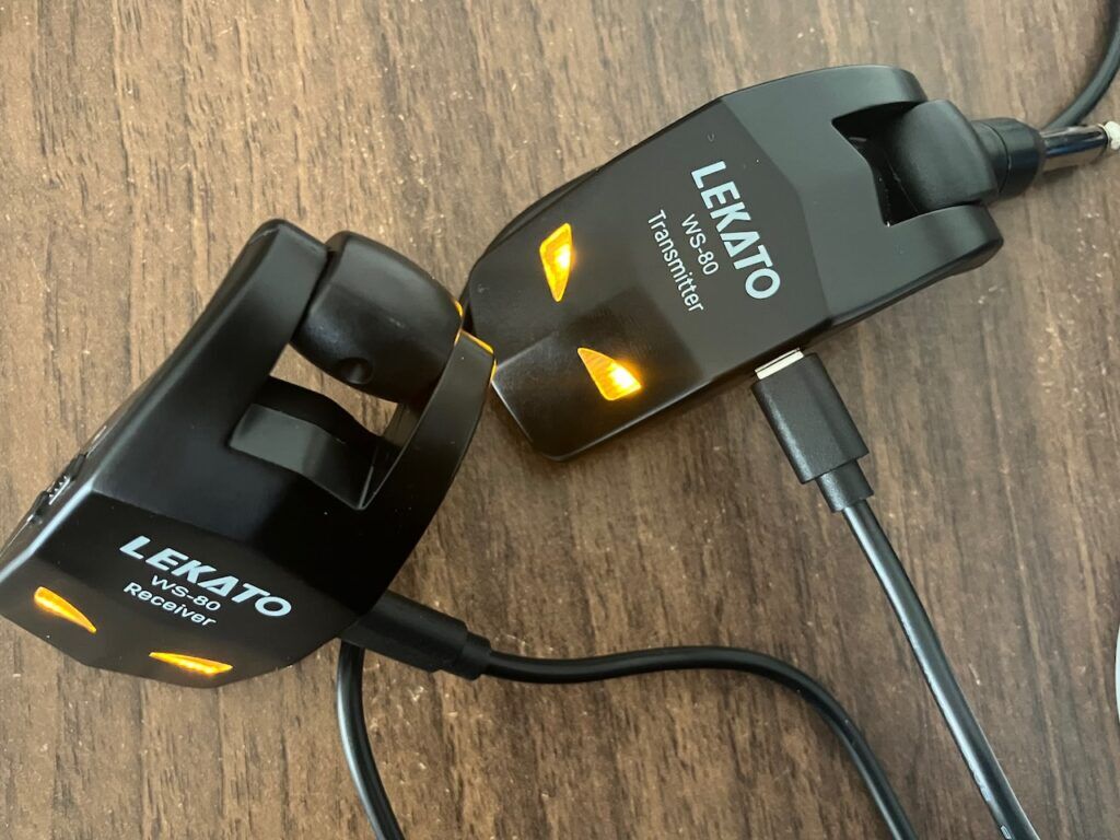
Imagine having not one, but two different devices that you constantly need to keep charged whether you are playing at home, rehearsing, or gigging somewhere.
Fu-sion-HA!
The plan was simple:
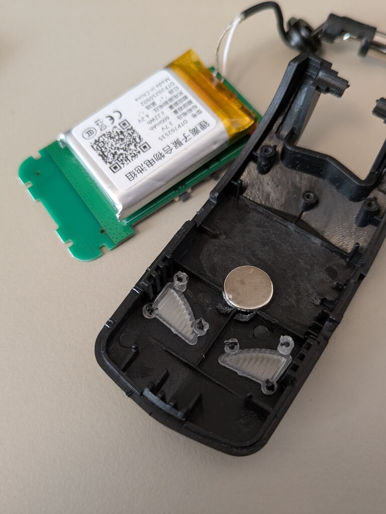
- Disassemble the transmitter.
- Put the transmitter into an enclosure.
- Add a voltage regulator (from 9V to 3.7V).
- Make the enclosure fancy.
- Play guitar more often instead of finding excuses not to do so.
After multiple attempts with the only 3D software I had ever used (Tinkercad indeed), I realized that if I wanted to build something cool, I needed to step up my game…
Yo ChatGPT, gimme more feature-rich alternatives to Tinkercad.
I can now explain this section’s title: I picked Autodesk Fusion.
To anyone trying to decide which 3D CAD software to learn, I can say that Fusion is honestly very handy and fairly easy to pick up for moderately complex 3D projects:
Lekato WS80 transmitter pedal
Features include:
- Slide-in design for the transmitter board
- Separate (isolated) compartment for the voltage stabilizer
- Standard 9V power barrel jack
- Standard 6.3 millimeter audio output jack
- Band selection button
- Connection status LED (kind of)
- USB charging port
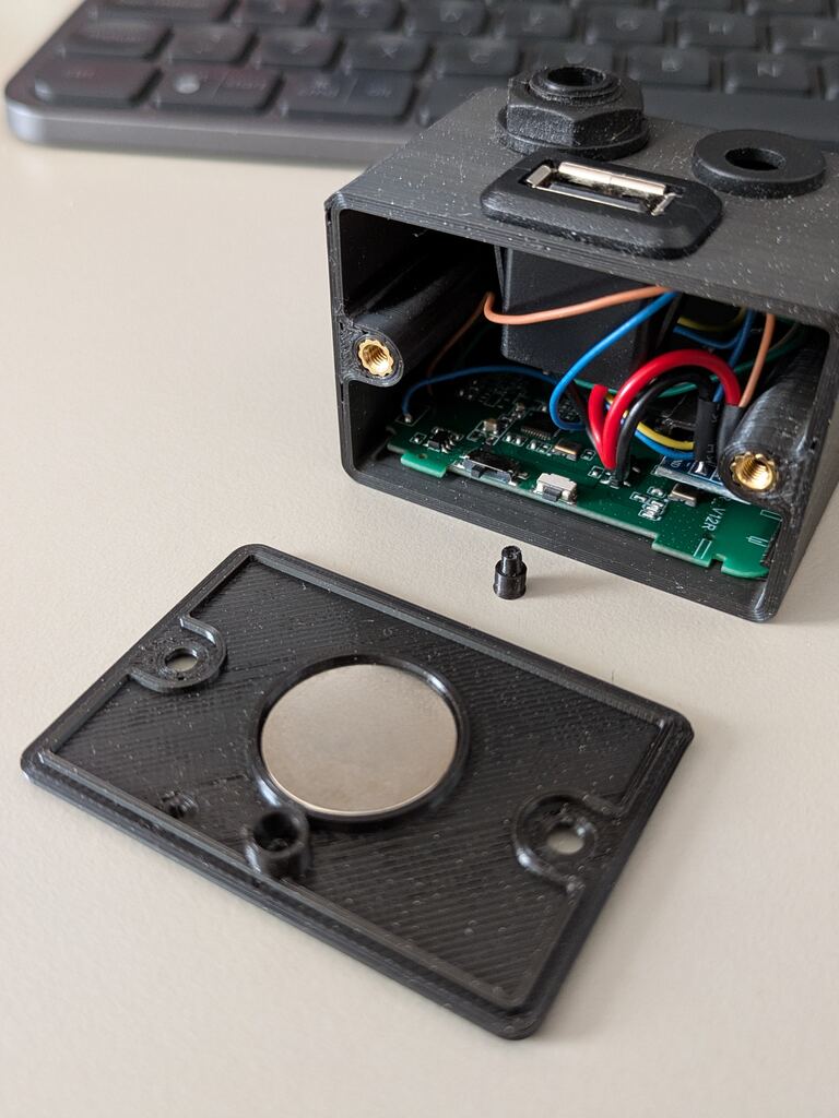
- Magnetic anchor for charging at rest
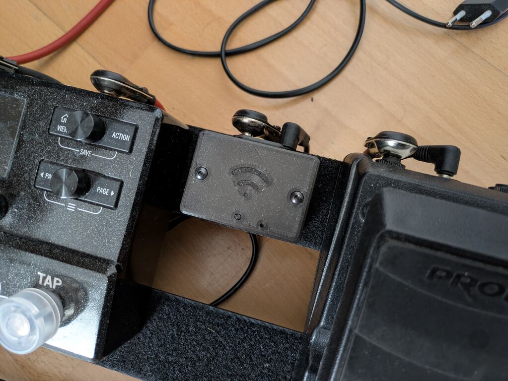
Slide-in design
Wanting to minimize the number of modifications required for the original Lekato board, I decided to secure the board with two simple rails. This also set the minimum size for the pedal.
Board orientation also matters if I want to keep the only other button besides the power button.
Standard pedalboard ports
The audio signal is routed using simple 6.3mm TS jacks.
Common guitar pedals use 9V center-negative DC jacks for power delivery.
Both ports can be found easily on Amazon, eBay, or any electronics reseller.
The Lekato board accepts USB-level input voltage, thus requiring a voltage stabilizer. I ended up using an off-the-shelf 5V linear voltage regulator based on the LM1117.
Switching regulators could inject some level of noise into the audio signal. The downside of linear regulators is heat dissipation, but the Lekato is a low-power board, so it can be ignored.
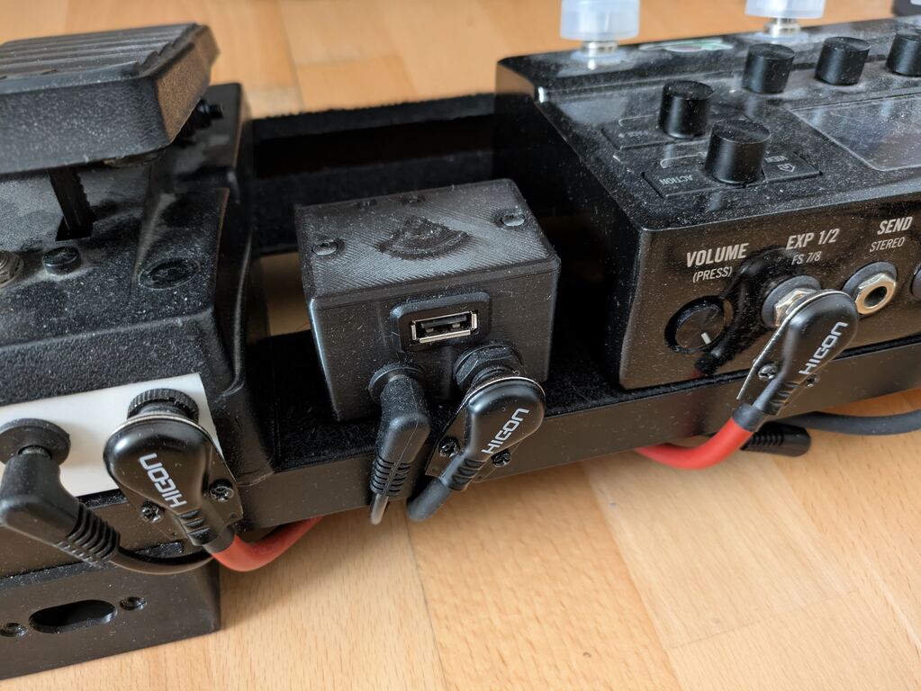
Charging at rest
I also added a USB Type-A port to the pedal to charge the Lekato transmitter during gigs.
I noticed that having a board leaning on the ground, silently waiting for a stranger’s foot to destroy it, was not a good idea.
I ended up adding two magnets: one inside the pedal, and one inside the transmitter. This way I can leave the transmitter module comfortably charging on top of the pedal without having to constantly keep an eye on band members’ feet.